
How FEA Helps Review Light Steel Frames and Roof Trusses
A light steel framing model shows the shape of a building. It does not, by itself, show how an assumed load travels through the roof and walls to the supports. Finite element analysis (FEA) gives engineers a way to examine that question: they define members, materials, connections, supports and loads in a model, then review the calculated displacements, forces and stresses for those stated assumptions.
The images below show wall framing and a roof truss in Vertex BD. They are calculation views of design models, not physical tests, certificates or evidence of local approval.
What must be defined before the calculation?
The model needs member geometry and sections, material properties, connections, restraints and support locations. Loads and their directions also need to be defined. Changing any of these inputs may change the output. Vertex describes its beam and frame FEA as a linear static analysis with a linear elastic material model. The software can calculate displacement, member forces, stresses and support reactions. Vertex FEA Manual
That makes the result specific to the modeled conditions. A useful review starts with the input questions: Which load cases and combinations were considered? How were the supports and connections represented? Do the sections and material properties match the proposed components? A screenshot rarely contains the complete answers.
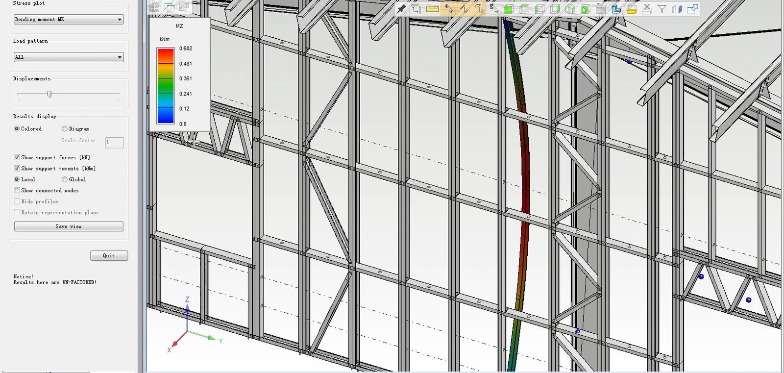
Figure 1. A wall-member MZ bending-moment view. Colours follow this plot’s kNm scale. The screen marks the results as “UN-FACTORED”; this image alone does not establish member capacity, connection adequacy or results under other cases.
What does a coloured result plot tell us?
Figure 1 identifies the selected result as “Bending moment MZ”, measured in kNm. The colours help locate the variation along the displayed members. Red occupies one end of this particular legend; it is not a universal failure warning. The result type, units, load pattern and model conventions must be read before any engineering comparison. The same software can display axial force, shear force, stress, displacement and reactions; those are different quantities. Vertex FEA Analysis
Loads also need context. Arrows around the roof truss show applied loads and directions in the model, but the image does not provide the full source, case definition or combination basis. It cannot establish a project’s wind, snow or other design actions on its own.
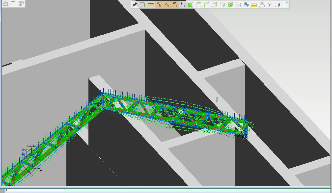
Figure 2. A roof-truss load setup view. The arrows visualise model inputs, not a physical load test. Load magnitudes, sources and combinations require the full analysis record.
How should the truss force plot be read?
In the truss result view, the selected plot is “Axial force N” and the legend is in kN. Different colours show variation among members in the displayed model. An engineer can use this view to identify members and joints for further checking. The screen again labels the results “UN-FACTORED”. This plot alone cannot establish final utilisation or show that the whole building has passed structural review.
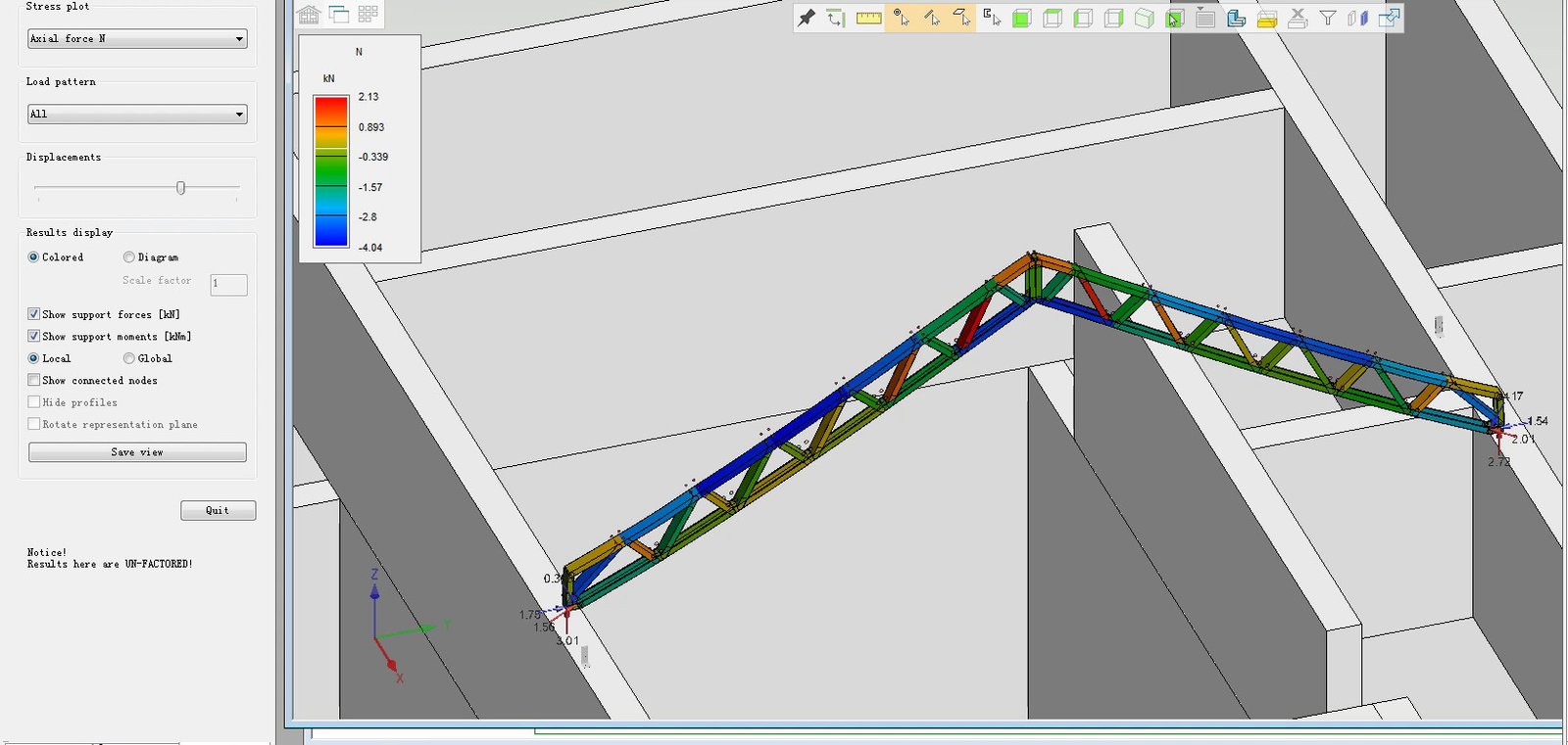
Figure 3. Axial-force view of the modeled truss. The colours correspond to this displayed kN range; they are neither material strength grades nor a compliance certificate.
FEA software may enlarge a displayed deformation to make its shape easier to see. The onscreen shape is therefore not necessarily drawn at the true displacement scale. Reviewers need the reported values, units and selected case, followed by checks of relevant limits, connections and the complete load path. Vertex FEA Analysis
Turning model review into a procurement decision
FEA can help a design and procurement team discuss where a question occurs. A material schedule still needs the building and site information, applicable actions, member and connection design, support conditions, drawing revisions and agreed supply scope. For an overseas project, a qualified local engineer should confirm the applicable code requirements, statutory approval and professional sign-off.
Halcyon Steel Homes can coordinate structural design development, material schedules and installation drawings with the client’s local engineer, based on the project drawings and confirmed supply scope. Developers, contractors and project buyers can share their building drawings, project location, building quantity, existing structural design basis, required material scope and target schedule to discuss a project material review.
Does red in an FEA plot mean the design has failed?
No conclusion follows from colour alone. Colour only has meaning against the selected result and its legend. The full inputs, load combinations, member and connection checks, and professional review are needed.
Can one FEA model establish suitability for other sites?
No. Site actions, geometry, supports, connections and local requirements may differ. Each new project needs its design conditions confirmed; FEA does not replace local engineering review or approval.